To change the true north. Firstly we need to change the view orientation to true north. Using this we can choose the angle to rotate the project, in this case i have chosen 37 degrees.
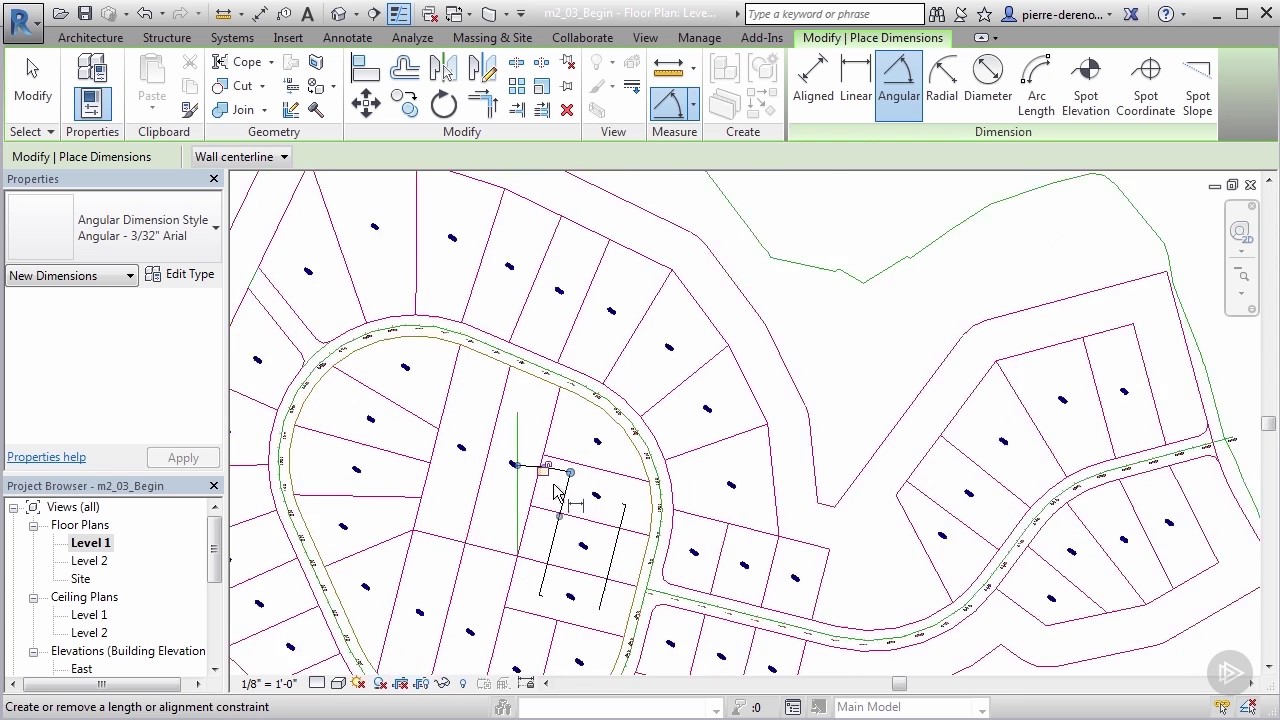
All that’s left is to change my view orientation back to. Draw then, a reference plane through the grid intersection at an angle the building is orientated on site. Measure the angle with horizontal (angular dimension). click on project base point and at align to true north put the measured angle value. the whole will rotate.
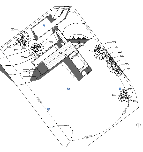
Now , select only the toposurface and rotate back with the measured angle. On the options bar, for angle from project to true north, enter a value to set the angle of rotation. For example, if the difference between project north (the top of the view) and true north is 45 degrees, enter 45.
The model rotates in the view to the specified angle. Select the dimension and convert it into a parameter with add label. Create a parameter, as shown:
Circles and lines that make up the north symbol, and rotate them to match the rotation of the reference line. After that, you will see a warning about “constraints not satisfied”. Click on remove constraints.
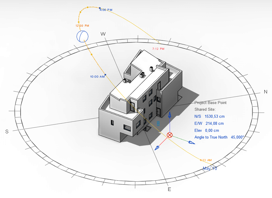
Set the angle of true north as it relates to the angle of project north in your model. Use a reference object to help you rotate the north position. This video demonstrates the following:
Place a reference element for north rotation. Relocate the center of rotation. Set the view to use true north or project north.
Transcript all projects have 2 north orientations. On the options bar, for angle from project to true north, enter a value to set the angle of rotation. For example, if the difference between project north (the top of the view) and true north is 45 degrees, enter 45.
The model rotates in the view to the specified angle. Revit angle to true north is broken. May 10, 2022, 05:14 pm.
We have found revit 2021 and revit 2022 if you rotate the angle to true north for each 1* it rotates 1* 0' 0. 00288. Works fine in 2020. Tested with new project > none > imperial as well as a couple of our active projects.
You do not have permission to view this gallery. On the options bar, for angle from project to true north, enter a value to set the angle of rotation. For example, if the difference between project north (the top of the view) and true north is 45 degrees, enter 45.
The model rotates in the view to the specified angle. Project north & true north. Revit lets users set two different plan orientations and allows users to individually define a plans orientation.
(i find less advanced users typically ignore this feature. ) the best use case for this feature is setting the floor plans to project north and using true north to show existing site orientation. If there is an angle set up between project north and true north in a project file and the model geometry has been drawn by fault in a view oriented to geographic north instead of project north, the orientation of the model elements will be incorrect in the model space of revit itself. Magnetic north, which likes to shift around and is typically a bit useless for the aec industry.
So, we draw in project north, survey / georeference in grid north, and solar analysis in true north. Out of the three important ones, revit supports only 2. The model rotates in the view to the specified angle.
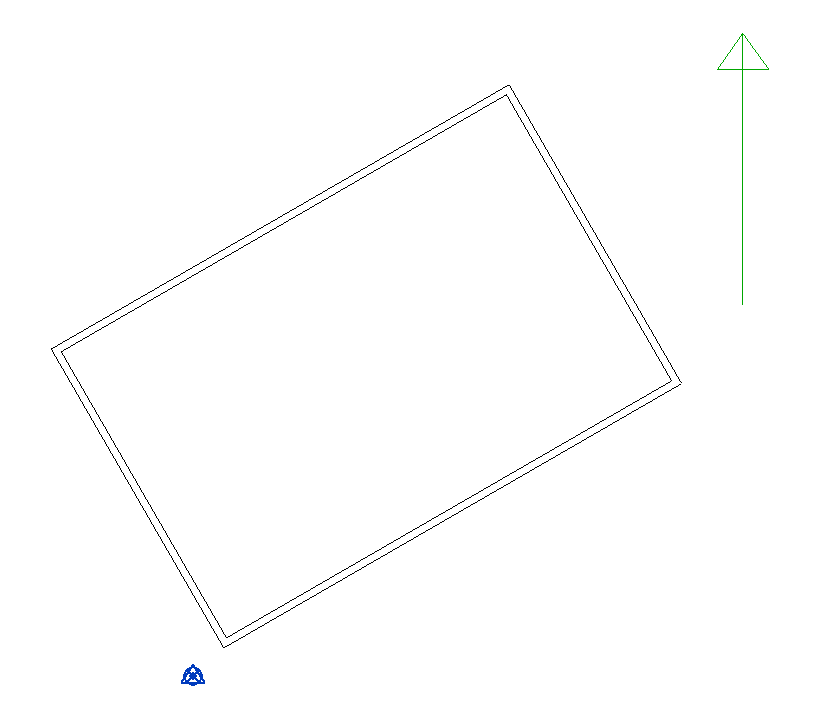
Rotate the model to true north graphically: Select the rotation control that displays at the center of the model, and drag it to the guide. Click along the guide to indicate the direction of true north.
Click again toward the top of the application window. The model rotates to the true north. All models have 2 north orientations:
Project north and true north. Project north is typically based on the predominant axis of the building geometry. It affects how you sketch in views and how views are placed on sheets.
When designing the model, align project north with the top of the drawing area. This strategy simplifies the modeling process. Follow the steps below.
Create a north arrow family that has an angle parameter called angle to true north. Place the north arrow family on a plan view that has the project north orientation displayed. Turn on the project base point on the plan view.
Open dynamobim and place the following nodes shown in the image below.